Controlling Servos from an Arduino


Introduction
Servos allow you to rotate an object to a given angle. This is done by sending them a Pulse-Width Modulated (PWM) signal, which is a way to emulate an analog signal by changing the duty-cycle of a series of digital pulses. This means that it turns a pin on and off fast enough that the connected components think they are being fed a continuous signal of varying amplitude.
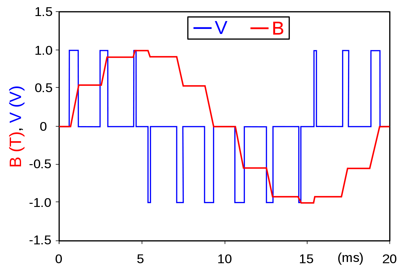
A PWM signal (source)
Because of the light-weight of servos (and their ability to turn to a specific angle), servos are used in a variety of places such as RC planes and cars, or even in model rockets such as my "Finnley" model rocket which uses servos to drive its two canards.

A rendering of my "Finnley" model rocket, which features 2 servo-driven Canards which are controlled by an Arduino-compatible board.
Connecting Servo to Arduino
Connecting a servo to an Arduino is quite simple. The first step is to figure out what each wires purpose is. Servos have 3 wires: Power, Ground, and Signal. While the coloring scheme of the wires on servos is not always consistent, ground will usually be black or brown and is always on the outside. Power is next to ground, and usually red, and signal is on the outside, usually white or yellow.

Servo wiring (source)
Once you've figured out which color corresponds to which wire on your specific servo, you can connect the servo to your Arduino. Conveniently, servo connectors use the same pin spacing as standard header pins, which means you can create your own servo connectors just by using header pins on perfboard. If this seems like too permanent of a solution you can also use male-to-female or male-to-male jumper wires.
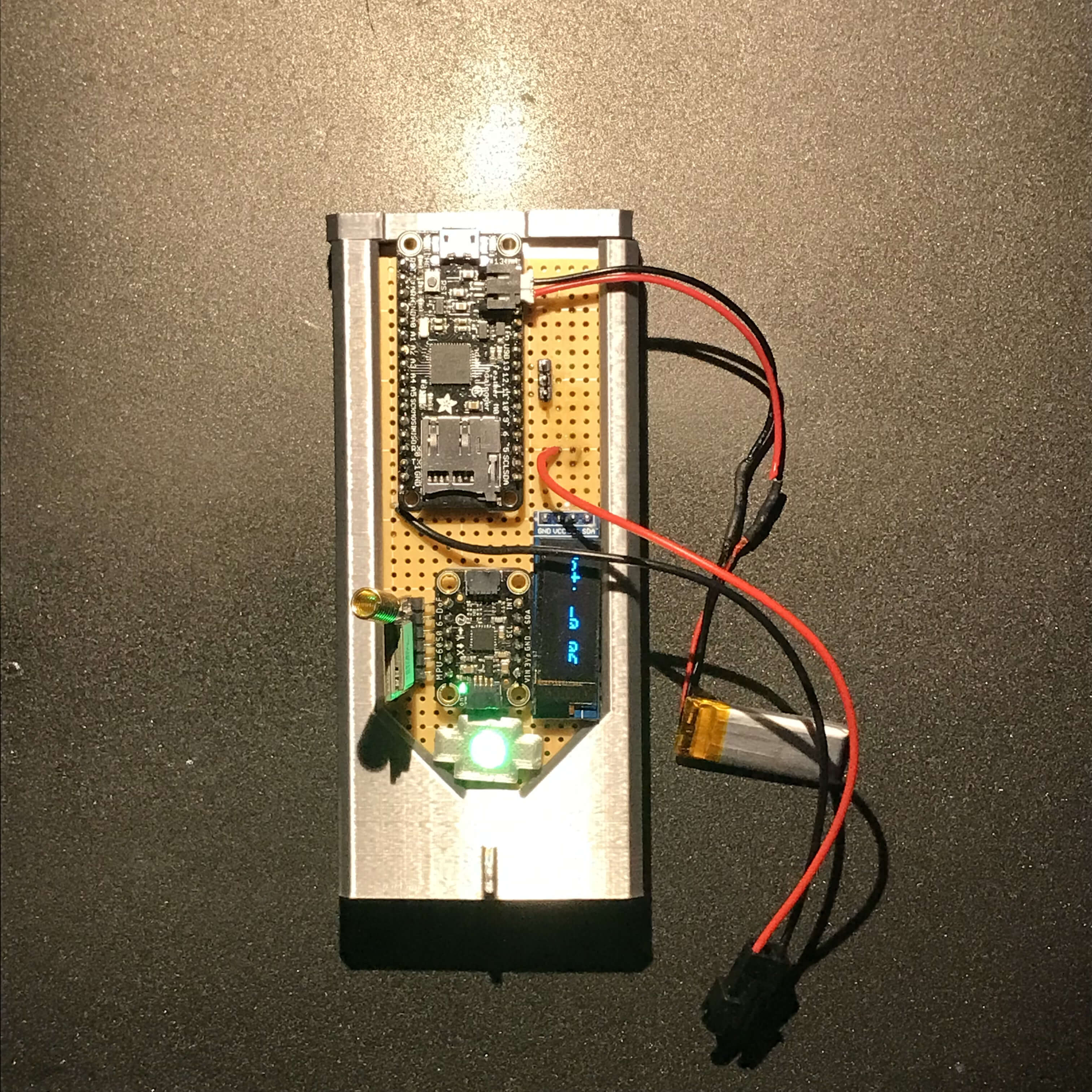
My homemade flight computer for my "Finnley" model rocket, which contained 2 servo connectors made from header pins soldered to perfboard.
As far as which wire connects to which pin, ground connects to ground, power connects to 5v, and signal connects to any PWM enabled digital pin.
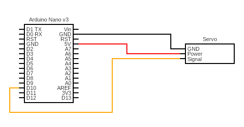
A circuit diagram of connecting a servo to an Arduino Nano
Controlling the Servo
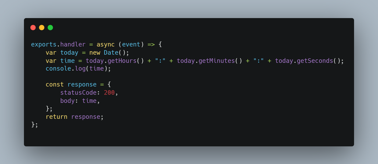
Controlling servos is made very simple with the help of the Servo Arduino library. The below program will make a servo on pin 10 turn from 0 degrees, to 90 degrees, and back to 0. In the beginning of the program before the setup function we import the Servo library and create a Servo object called "servo1". Then, inside of the setup function we use the servo1.attach() function to have the servo1 Servo object write to the servo on pin 10. Lastly, we use the servo1.write() function to turn the servo to the given angle.

A simple program to control a servo on pin 10
Next Steps
Now that can to control a servo directly, you may want to look into more advanced things such as controlling a servo via a PID loop to react to a sensor reading in order to control a model airplane or a robotic arm. Eventually you may find that the current draw of your servo(s) exceeds the maximum current rating of the pins. In this case you can use external batteries to power your servos as long as the voltage is within the voltage range of your servos, and the external voltage source is grounded to your Arduino.
