Designing Propellant Tanks for Rocketry


Introduction
If you plan to build larger rocketry projects such as liquid or hybrid engines, you'll eventually have to design and build propellant tanks or other pressure vessels. While games such as Kerbal Space Program may make this seem like a trivial task, in reality it is a bit more involved. This tutorial will teach you the basic principles behind designing a propellant tank for a rocket, such as determining the shape, size, and material; but if you plan to actually build a propellant tank you should do more research such as reading through Rocket Propulsion Elements and similar texts. The additional ground support equipment required to fill and pressurize the tank, as well as the sensors and lines you may want to connect to it will be left outside of the scope of this tutorial.
Tools Required
As this tutorial will only cover designing a propellant tank, the tools required are quite flexible. In this tutorial I will be using MATLAB to perform the calculations, and Fusion 360 to create a CAD model . Both programs are freely available to me, but you can also use Python instead of MATLAB if you do not have access. As far as the code snippets shown below, I will be showing code snippets of the section I am adding to the program but all of the code snippets belong to the same program and will reference variables defined in previous snippets.
High Level Overview
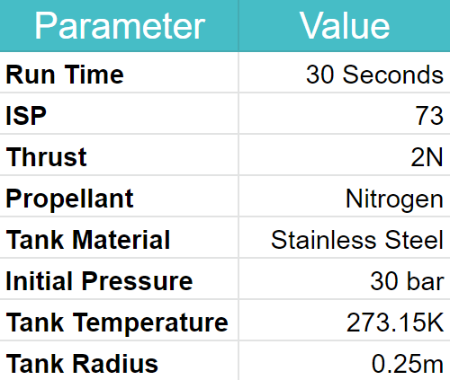
While this is a somewhat complex problem, breaking it down into smaller sub-problems will make it much easier to solve. First, lets talk about what the "givens" will usually be for a problem like this. In order to simplify this a little, we will use a theoretical scenario. In this scenario, our end goal is to store enough fuel to run our pressure-fed cold gas thruster for 30 seconds. We are using a cold gas thruster as this will simplify the later calculations due to the fact that the engine uses a single gas as fuel. This engine has a specific impulse of 73, an average thrust of 2N, uses Nitrogen gas, and the propellant tank we are designing will be made from Stainless Steel. As the engine is pressure-fed, its thrust will decrease as the propellant tanks pressure decreases. For this tutorial, though, we will just use the average thrust to keep things less complicated.
My Methodology
In order to solve this problem, it would first make sense to calculate the mass flow rate over the duration of usage, which can then be used to calculate the total amount of fuel needed. After we have this, we can then find the amount of volume this fuel will occupy at the determined tank pressure and temperature, which can then be used to calculate the required wall thickness to safely store this fuel. Lastly, we can find the final dimensions and mass of the fuel tank.
Mass Flow Rate
First, let's calculate the mass flow rate from our propellant tank. Again, for this example, we are assuming the thrust to be the average thrust from our engine over the duration of the burn, so this may not be as accurate as it otherwise could be. With this established, we now can talk about mass flow rate. Mass flow rate is the mass of fuel being removed from our fuel tank per second, and in our case it can be calculated by dividing the average thrust by the specific impulse multiplied by the gravitational constant (source). This is important for us as we will later use this to find how much total fuel we will need. The units for mass flow rate will be KG/Sec, and mass flow rate itself can be denoted as an m with a dot on top.
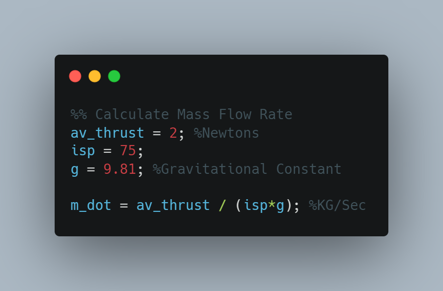
This gave me a value of 0.0027 kg/sec.
Fuel Mass
Now that we have the mass flow rate from our propellant tank, we can calculate the total mass of fuel required. This is fairly simple as it will just be the mass flow rate multiplied by the run time of the engine.
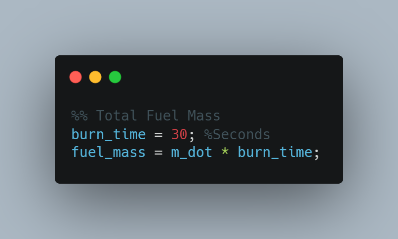
This gave me a value of 0.0815 kg.
Finding Volume
Next, we are ready to find the volume that the fuel will take up at our desired tank pressure and temperature. In practice, this will depend on which (if any) systems you have for regulating tank pressure, as fluids tend to warm up as the pressure increases, and become less dense as they warm up. To simplify this tutorial, we are going to choose a temperature that the propellant will initially be stored at, assuming that there is some system in place to make sure the tank is at that temperature when fully fueled.
Knowing this, let's now find the fuel volume. First, we need to find the molar mass of the propellant in order to determine the total amount of moles of propellant. This can be done by multiplying the mass we found in the previous step by its molar mass, which would be found in the periodic table.
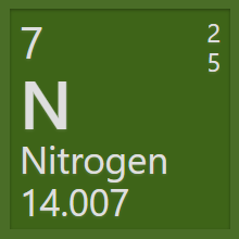
Here is a screenshot of Nitrogen (our propellant) in the periodic table, which has a molar mass of 14.007 kg/mol. With this information, we are now ready to start finding the volume! Below you can see the Van Der Waals equation (source). This equation relates the pressure, volume, moles, and temperature together for non-ideal gasses. We have to use this equation instead of the ideal gas law because of the high pressures and possibly low temperatures.

You may see that this equation also contains an a and b variable. These are the Van Der Waals constants. They can be found here, but for Nitrogen A is 1.370 and B is 0.0387. Due to the complexity of this equation, it is quite hard to rearrange it for V. Because I am using MATLAB, I will just use the equation solver instead. For P we will use 30 bar, for n we will use the previously found molar mass multiplied by the fuel mass, for R we will use 0.083144 (source), and for T we will use 273.15K.
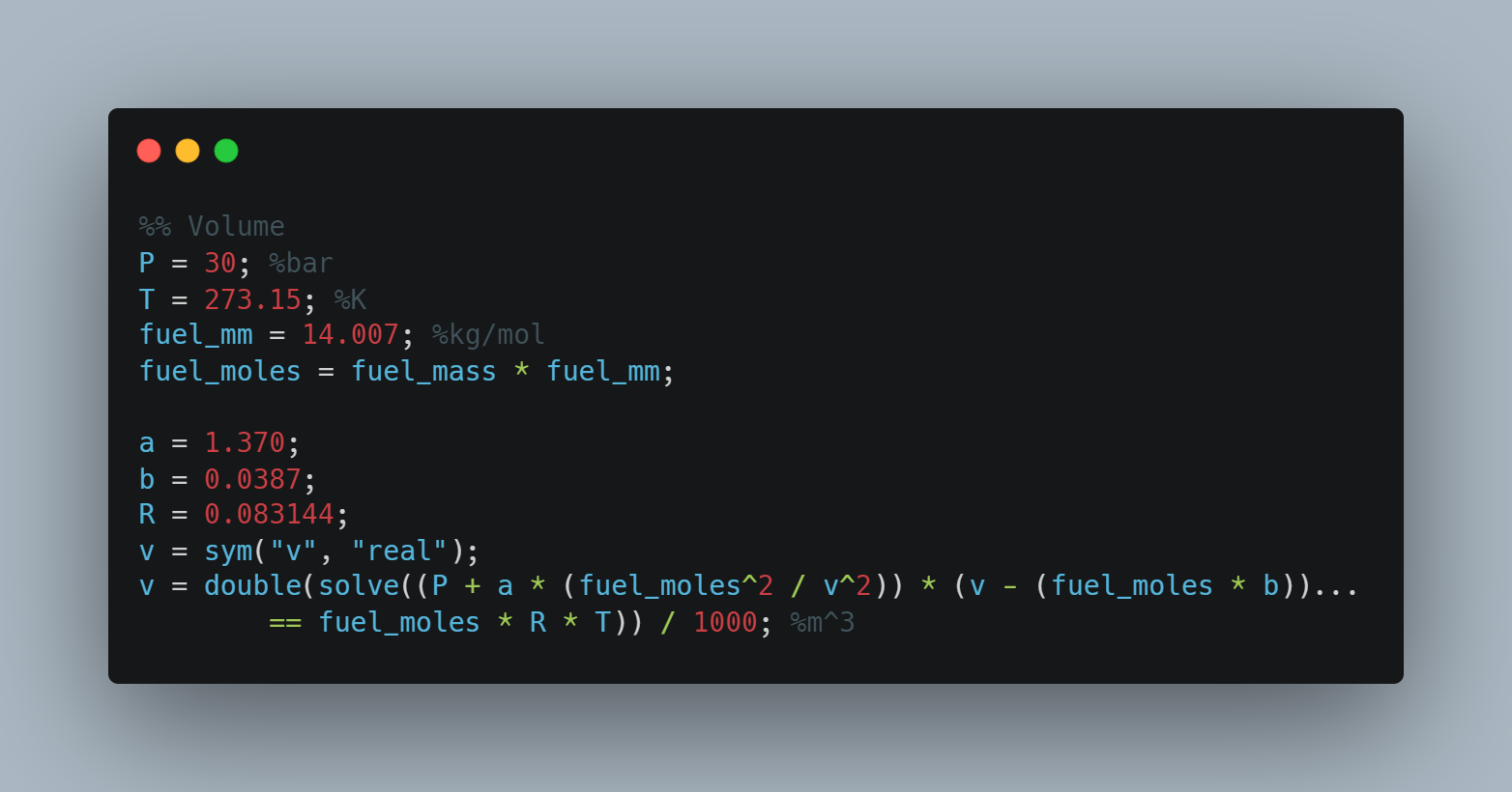
This gave me a value of 0.0008 m^3. This is a small value, but we only wanted to run our engine for 30 seconds so it makes sense.
Wall Thickness
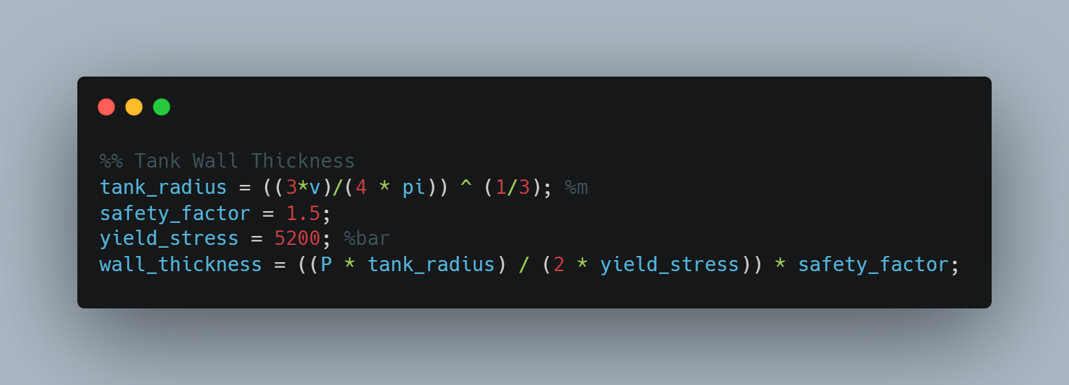
Now that we have the volume, we can calculate the required wall thickness. As with all things in engineering, making this decision is a tradeoff, as too thick of a wall thickness will greatly increase the tank mass, and too thin of a wall thickness can hurt the reliability of the tank, and even eventually cause it to fail. Because of this, engineers have come up with the concept of a Safety Factor. The safety factor is how many times stronger the material, or in our case the propellant tank, is than what it needs to be. You will have to do your own research to determine what your safety factor should be, but for this tutorial we will use 1.5. Next, let's talk about the concept of stress. Stress is a measure of what a material feels from outside forces, and is measured as a pressure. This pressure is different from the pressure within the tank, but the two numbers are related to each other.

The above equation solves for the stress in a spherical propellant tank. T is the wall thickness, p is the pressure within the tank, r is the tank radius, and sigma is the yield strength of the material being used for the tank wall. This equation as we have it right now would just give us the wall thickness without any safety factor, meaning a slight overpressure or a temperature that is slightly different would cause it to burst. To fix this, we can add our safety factor by multiplying the right side of this equation by our safety factor.
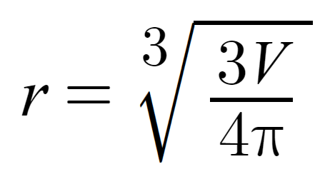
As you may have noticed already, the above equation actually has two unknowns: the wall thickness which we are solving for and the tank radius. To fix this, we can find our tank radius as we already know what the volume of the propellant inside is. To do this, we will just use the equation for the volume of a sphere, rearranged to solve for the radius.
Lastly, according to this website, the yield strength of cold-rolled stainless steel is 520 MPa, but for this equation to work the units of yield strength need to match the units of tank pressure. Since our tank pressure is in bar, we can convert the yield strength of 520 MPa to bar by multiplying by 10; which gives a value of 5200 bar. Now we're ready to implement this in our program!
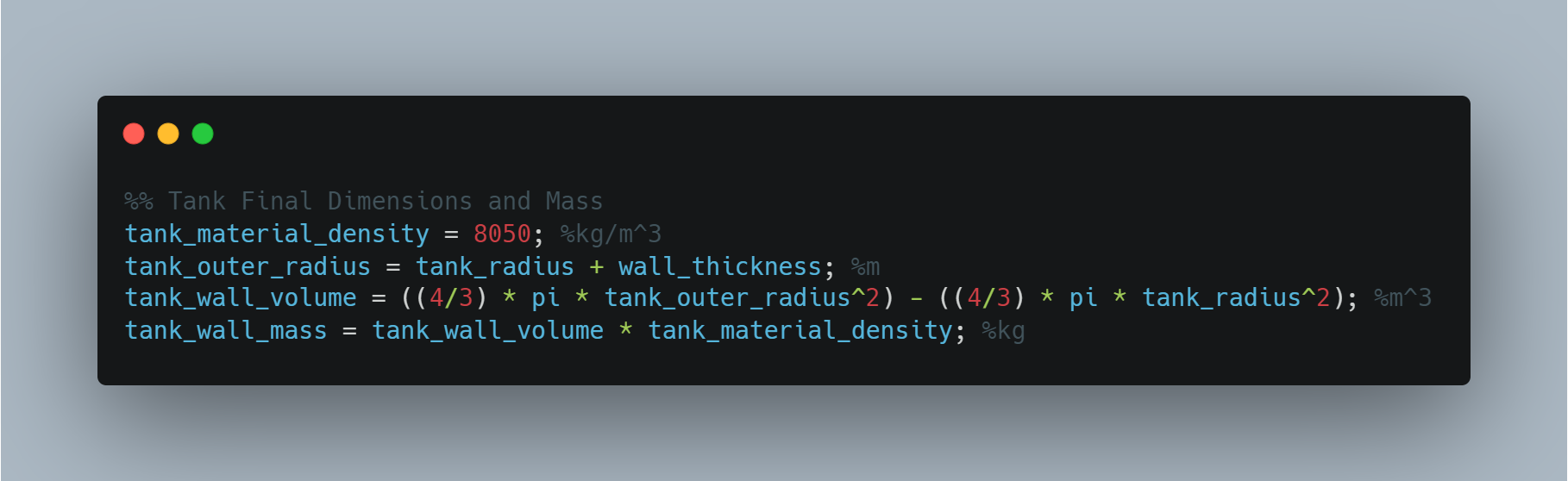
Final Dimensions
Now that we have calculated everything else, we are finally ready to determine the final dimensions and mass of our propellant tank! We have the inside radius and the wall thickness so this will be quite trivial. First, we can find the outer radius by adding the wall thickness to the inside radius. After that, we can find the volume of material used to create the walls by finding the volume of the outside of the spherical tank and subtracting the volume of the inside, which will just leave us with the volume of the walls. After that, we can multiply that volume by the density of the material used to construct the tank (in our case stainless steel), which will give us the mass of the tank!
Next Steps
Now that you know the basics of propellant tank design, there are a few things you can do to improve the fidelity of these calculations. The biggest thing you can do is to try to simulate the mass flow over time that is required by your engine. You can also look into other tank designs, such as capsule and toroidal tanks. Lastly, for liquid engines you will have two (or maybe even three) propellants, where each propellant will need its own tank. In this case, you will need to determine what ratio the engine will be running at, and thus what the mass flow of each propellant is. Good luck, the sky is (not) the limit now!
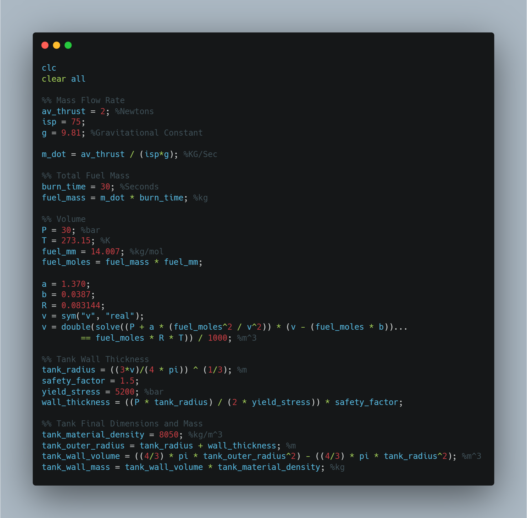
Here is the full program: